Formula SAE · Structural design
Topology-Optimized Front Wing Mount
A 6.4% lighter mount with 2.11× the bending stiffness under the same 150 lbf load case
01 / Ownership
Take ownership of a visible structural problem and demonstrate engineering judgment.
The 2026 frame and front wing required wider mounting-hole spacing than the previous car. The mount still needed to be light, stiff, and practical to manufacture.
I volunteered for the redesign because I wanted to demonstrate my analysis skills, establish credibility within the team, and show that I could carry a structural component from problem definition through verification.
02 / Analysis strategy
Choose the workflow that supports faster iteration.
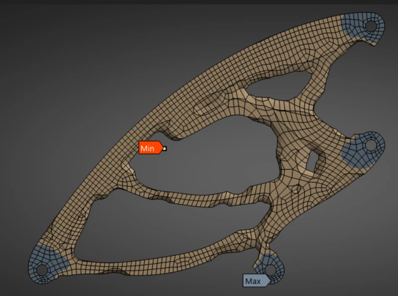
I evaluated multiple topology-optimization workflows before moving the study into SolidWorks. Its direct connection to the CAD model and my familiarity with the software let me iterate more quickly while keeping the design and simulation work connected.
The SolidWorks topology result exposed the primary load paths between the wing and frame mounting points. I used that geometry as engineering evidence, not as a finished component.
03 / Load case
Compare both designs under the same deliberately severe vertical load.
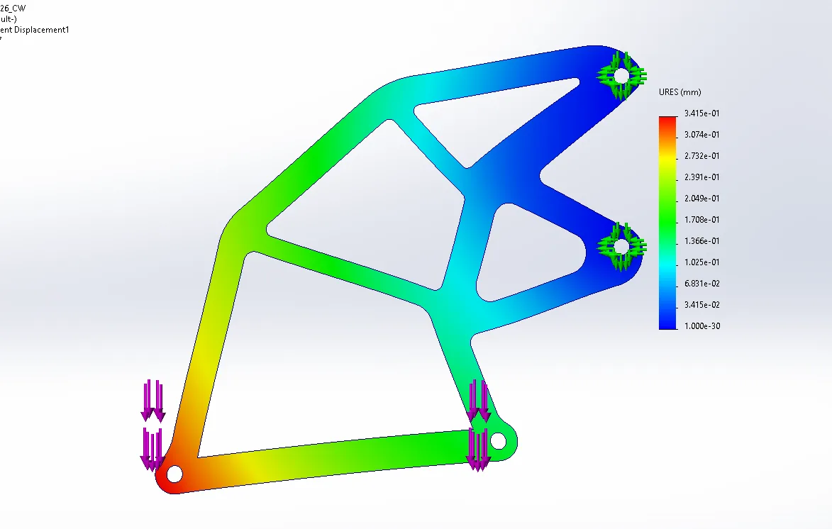
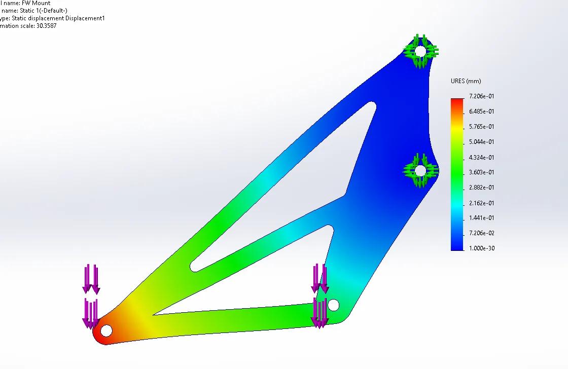
I fixed the frame-side mounting holes and applied 150 lbf downward across the wing-side holes. The load represented a conservative case similar to a person stepping on the front wing.
A temporary 0.5-inch bridge connected the wing-side mounting holes only in the analysis model. It represented the constraint created by the installed wing and was not part of the manufactured bracket geometry.
- Compared the 2025 baseline and 2026 redesign with the same load and boundary conditions.
- Evaluated peak resultant displacement as the stiffness comparison metric.
- Did not create a separate lateral buckling load case because the installed steel cable cross-bracing supports that mode.
04 / Manufacturable rebuild
Translate the organic result into controlled, waterjet-ready CAD.
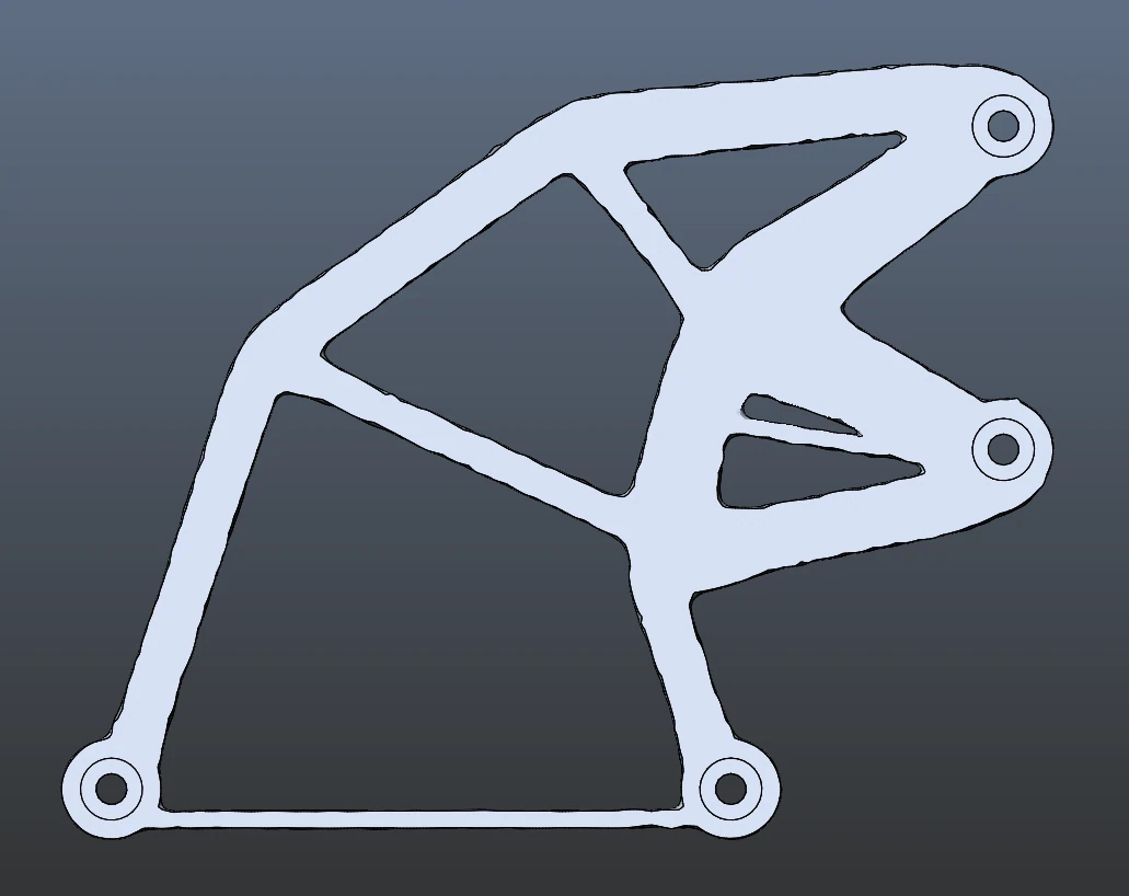
The raw topology output contained irregular edges and small features that were not appropriate for a finished plate component. I rebuilt the load path as a simpler parametric profile with continuous webs, practical radii, and geometry suitable for waterjet cutting.
This step preserved the structural logic of the optimization while producing editable CAD that the team could dimension, review, and manufacture.
05 / Results
A lighter mount, less than half the displacement, and a leadership opportunity.
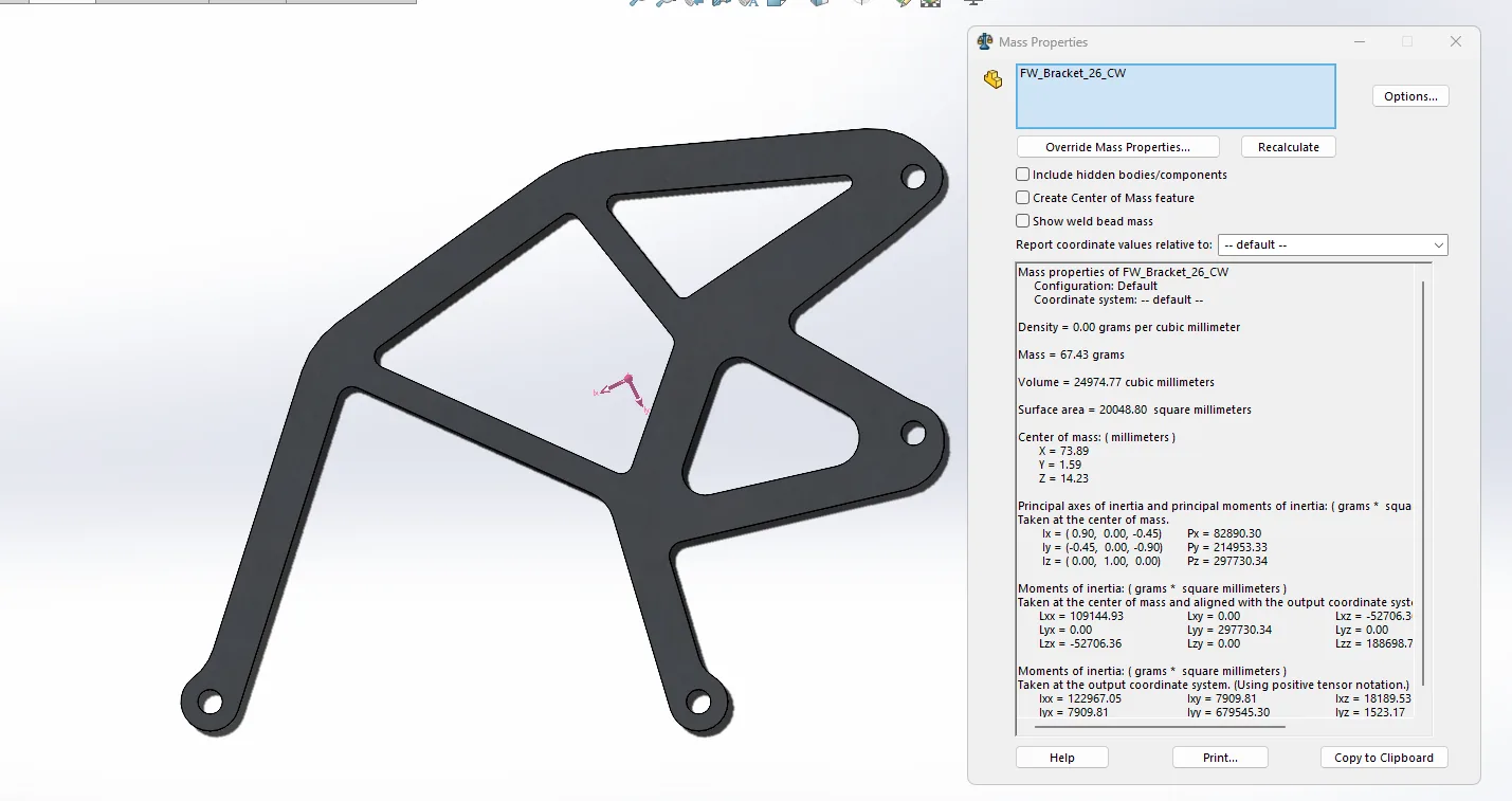
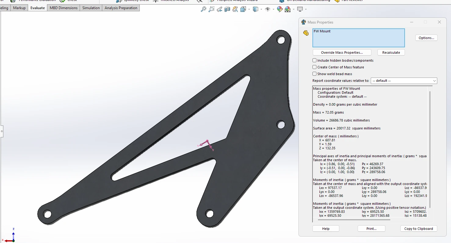
The final design reduced mass from 72.05 g to 67.43 g, a 6.4% reduction. Under the same 150 lbf load case, peak resultant displacement fell from 0.7206 mm to 0.3415 mm, a 52.6% reduction. That corresponds to 2.11 times the baseline bending stiffness.
The work demonstrated both engineering judgment and follow-through, and it contributed to my nomination as the team’s 2027 Frame Lead.
The mount was not manufactured because the team did not run an aerodynamic package that season.
Tools and methods
- SolidWorks
- SolidWorks Simulation
- Topology optimization
- Finite element analysis
- Parametric CAD
- Waterjet DFM