South Dakota Mines · Structural design
South Dakota Mines Bridge Design Competition
A sub-75 gram printed bridge refined through FEA and destructive testing
01 / Constraints
Carry the largest center load with less than 75 grams of PLA.
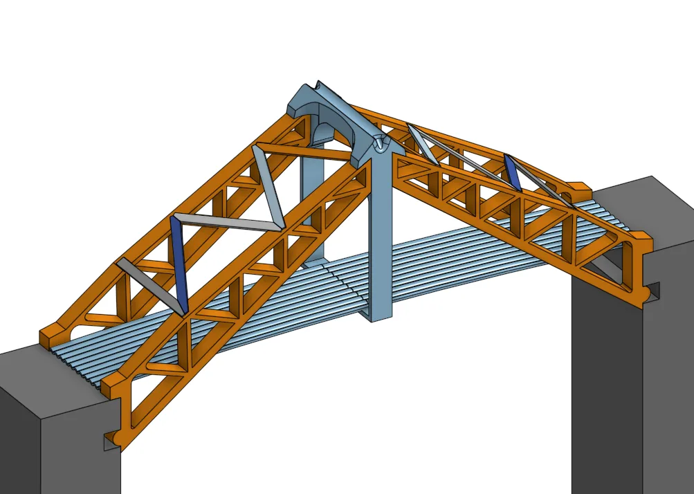
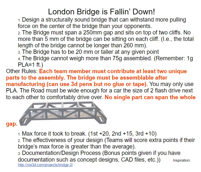
The bridge had to span a 250 mm gap, stand at least 20 mm tall, provide a usable road surface, and weigh no more than 75 grams. No single printed part could cross the full span, and the completed bridge had to be assembled without glue or tape.
Those rules made connections, buckling resistance, print orientation, and material placement as important as the overall truss shape.
02 / Iteration
Use simulation to choose what to print, then use testing to challenge the simulation.
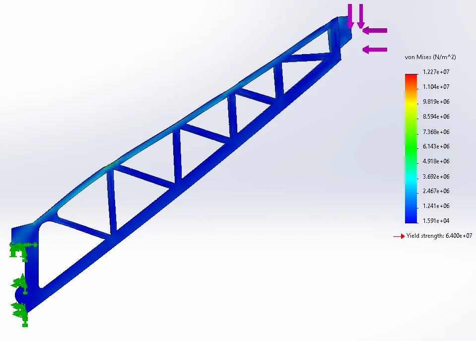
We modeled the bridge in Onshape, evaluated critical members with SolidWorks finite element analysis, and printed prototypes to expose real failure modes that the idealized model could not fully capture.
Diagonal bracing was added where early versions showed instability, and the multi-part connections were refined so assembly constraints did not interrupt the primary load path.
03 / Result
Twice the second-place load in competition, then nearly twice that again.
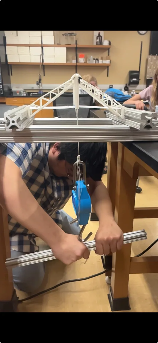
The competition bridge supported 427 N, twice the load carried by the second-place bridge. Continued testing after the event produced a maximum load of 845 N, or approximately 190 pounds.
The progression from CAD to FEA to destructive testing made the bridge a compact lesson in lightweight structures: the best design came from repeatedly connecting analytical load paths to observed failure behavior.
Interactive model
Inspect the geometry.
Orbit the bridge and select the numbered callouts to follow the structural load path.
Loading bridge model…
Design callout
Multi-part center joint
The center connection satisfies the rule that no single printed part may span the entire gap while transferring the peak applied load into both trusses.
Drag to orbit · scroll to zoom · right-drag to pan
Tools and methods
- Onshape
- SolidWorks FEA
- PLA
- 3D printing
- Prototype testing
- Structural design