Personal · Aerospace
RC Airplane Prototyping
How hard could designing an aircraft be? Very hard, as it turns out.
01 / First attempt
The first prototype made the consequences of poor balance impossible to ignore.
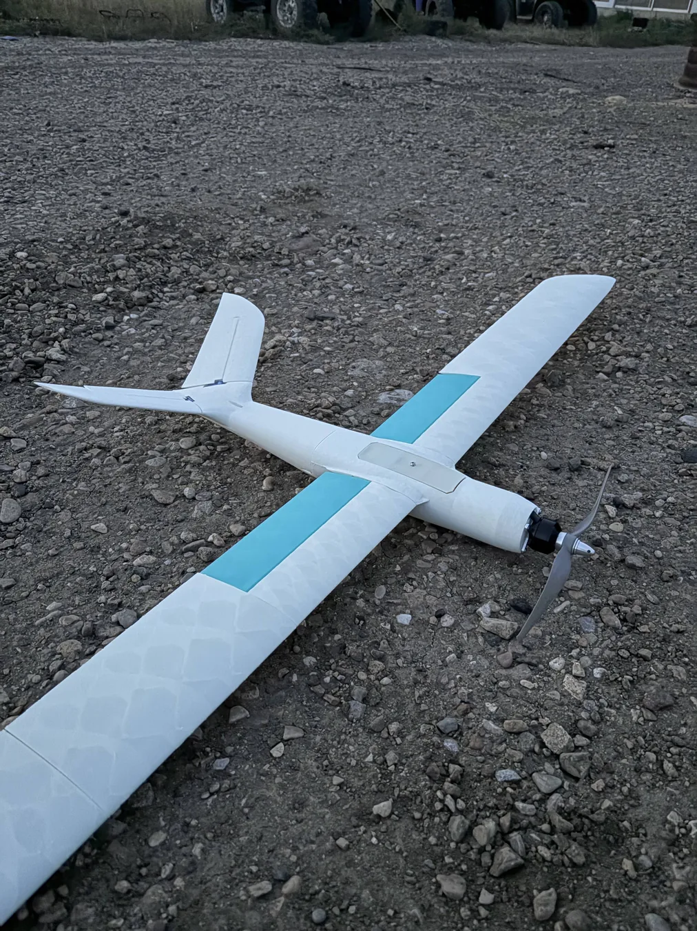
I began by quickly modeling a 3D-printed aircraft in Fusion 360 and packaging it around hobby electronics. The PETG airframe had a wingspan of about 300 mm and weighed roughly 1,600 g, making it extremely dense for its size.
The aircraft was also severely tail-heavy. On its first launch it pitched nearly vertical, hovered briefly, rolled backward, and nosedived into the gravel. That failure showed that a plausible shape was not enough. I needed to understand stability, balance, and weight as a connected system.
02 / Learning loop
Replace guesswork with stability analysis and inexpensive flight experiments.
I researched aerodynamic stability and began using OpenVSP to evaluate pitch and roll behavior before committing to another powered build. I studied how the center of mass related to the center of lift and how wing dihedral contributed to passive roll stability.
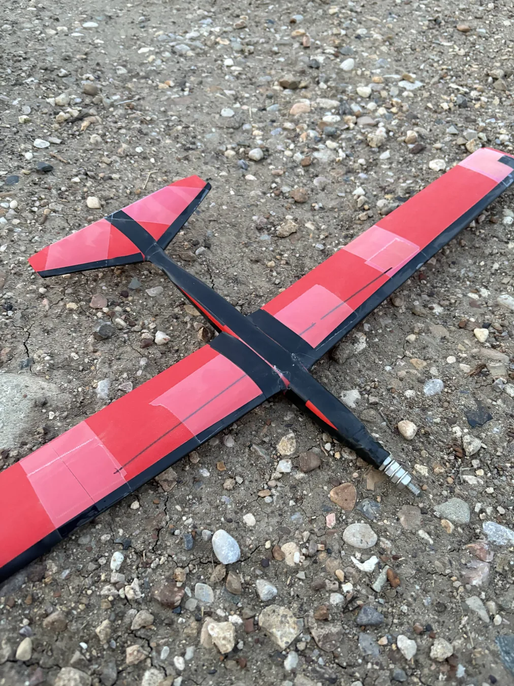
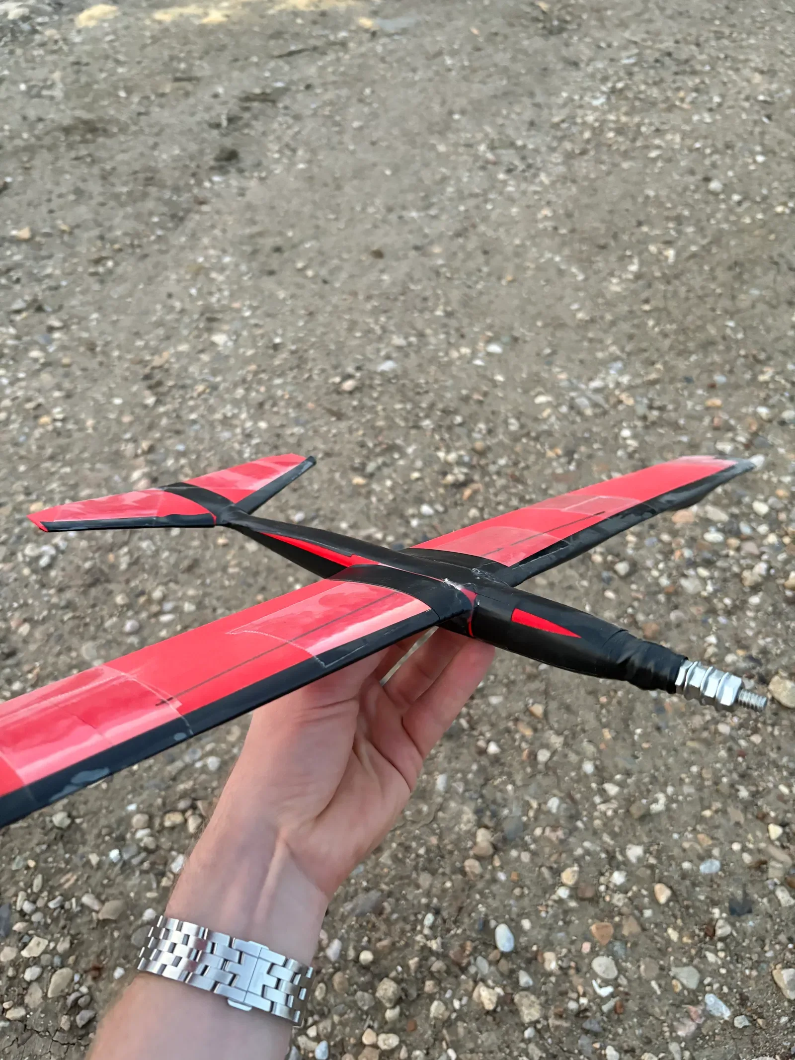
I then printed multiple lightweight foaming-PLA gliders to compare the predicted trends with physical behavior. Moving the center of mass and changing the geometry made the effects on dive tendency and general stability tangible.
03 / Second design
Increase the wingspan while removing one kilogram from the aircraft.
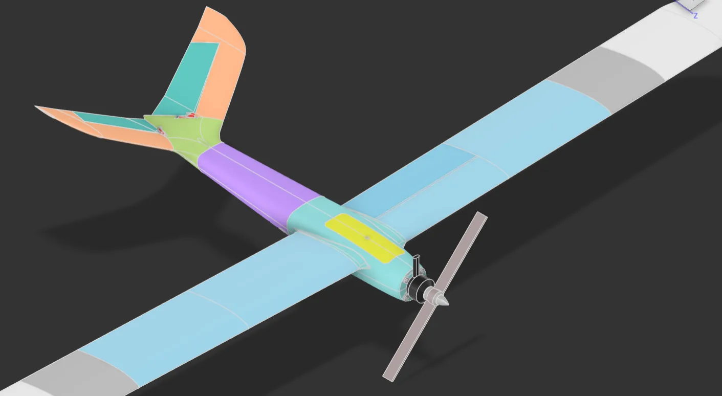
For the second powered design, I refined the configuration in OpenVSP until the predicted stability and center-of-gravity location were reasonable. I exported the resulting geometry into Fusion 360 and used it as the basis for the detailed airframe.
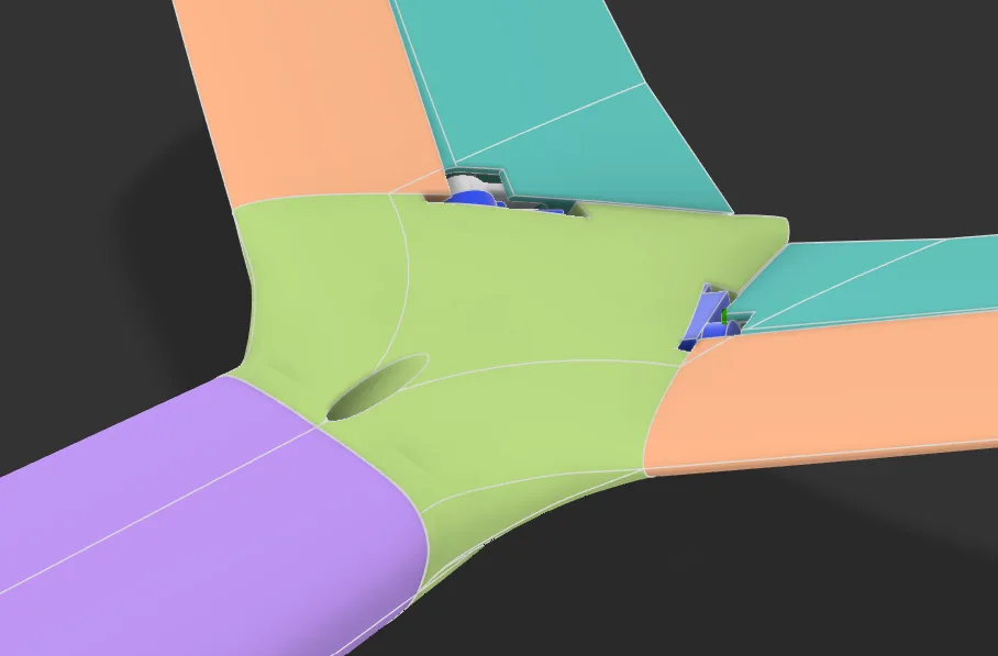
The redesigned aircraft grew to a 1,000 mm wingspan while its mass fell to about 600 g, a 62.5% reduction from the first attempt. I learned surface-modeling techniques to create the smooth junction between the rear fuselage and tail surfaces.
04 / Structure and printing
Tune the printed shell and reinforce only the load-carrying structure.
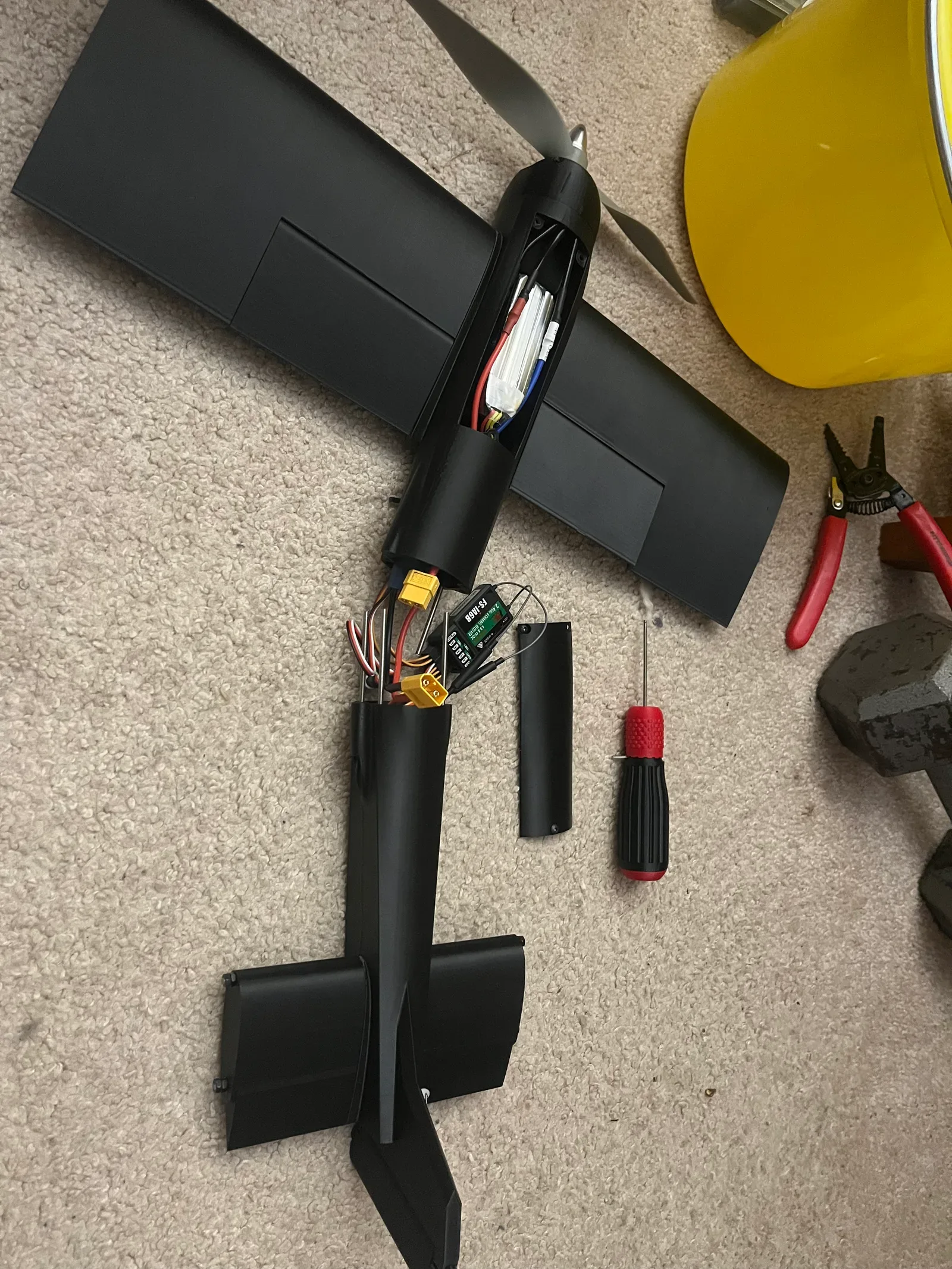
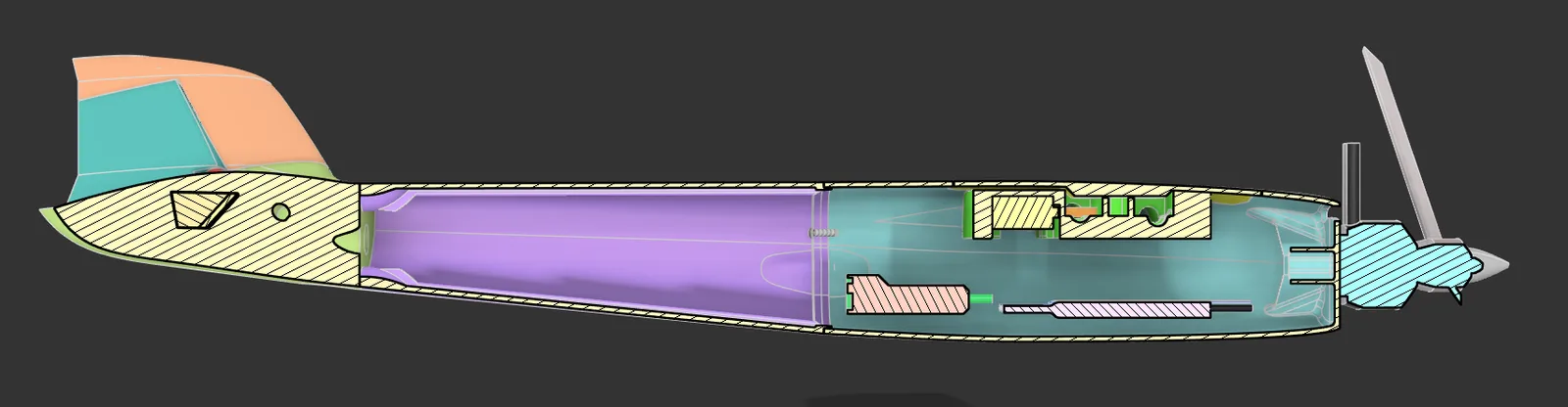
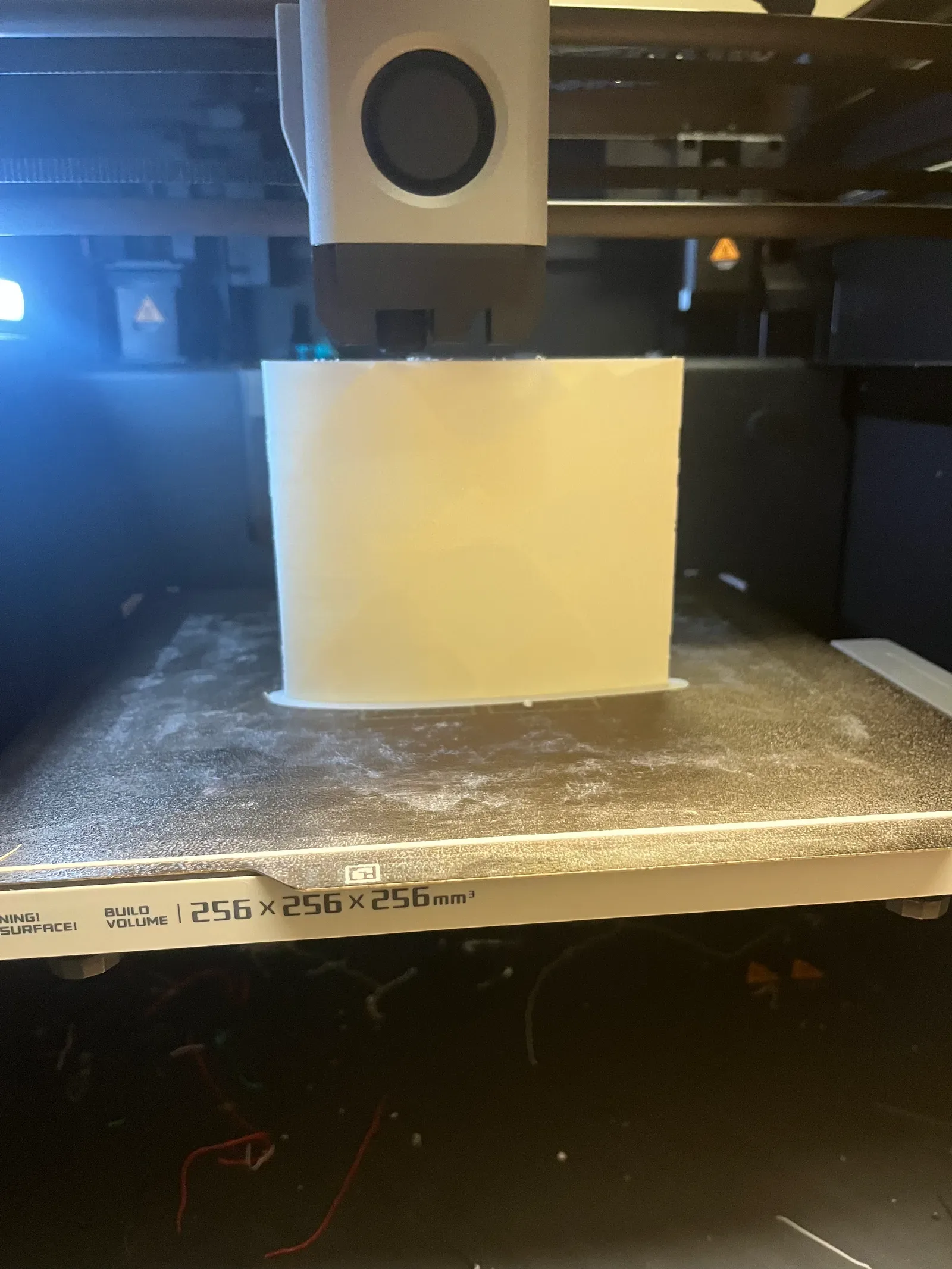
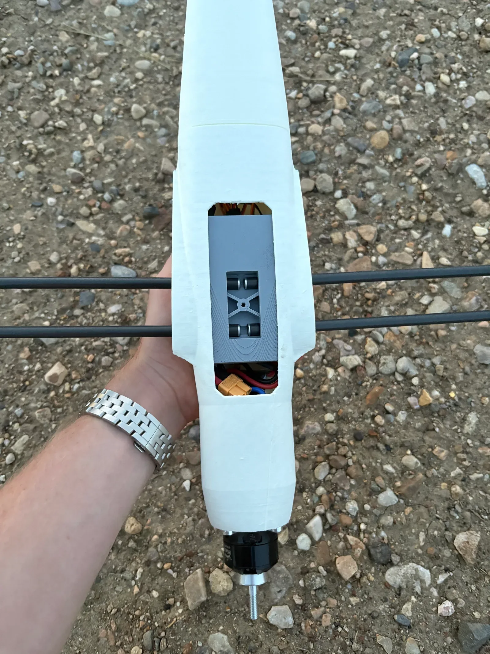
I adjusted the slicer settings for foaming PLA to balance shell stiffness against mass and used carbon-fiber rods as wing spars for lightweight rigidity. The internal CAD packaged the battery, receiver, linkages, and motor while preserving a practical center-of-gravity location.
This combination let the printed skin define the aerodynamic surface while the carbon spars carried the primary wing-bending loads.
05 / Outcome
A better-engineered aircraft with an honest limit on the result.
The second design was completed but never flight-tested, so I do not claim a successful powered flight. Its value was the engineering progression from an uncontrolled first attempt to a lighter, analysis-guided design with deliberate stability and structural decisions.
The project established a practical foundation in aircraft balance, dihedral, aerodynamic stability, lightweight CAD, surface modeling, and slicer-driven structural design.
Tools and methods
- OpenVSP
- Fusion 360
- Surface modeling
- 3D printing
- Foaming PLA
- Carbon-fiber spars
- Slicer optimization