Personal · Mechanical systems
Custom RC Car
An ambitious printed drivetrain built around a 4 hp electric motor
01 / Challenge
Design the complete mechanical platform after learning electronics on a borrowed chassis.
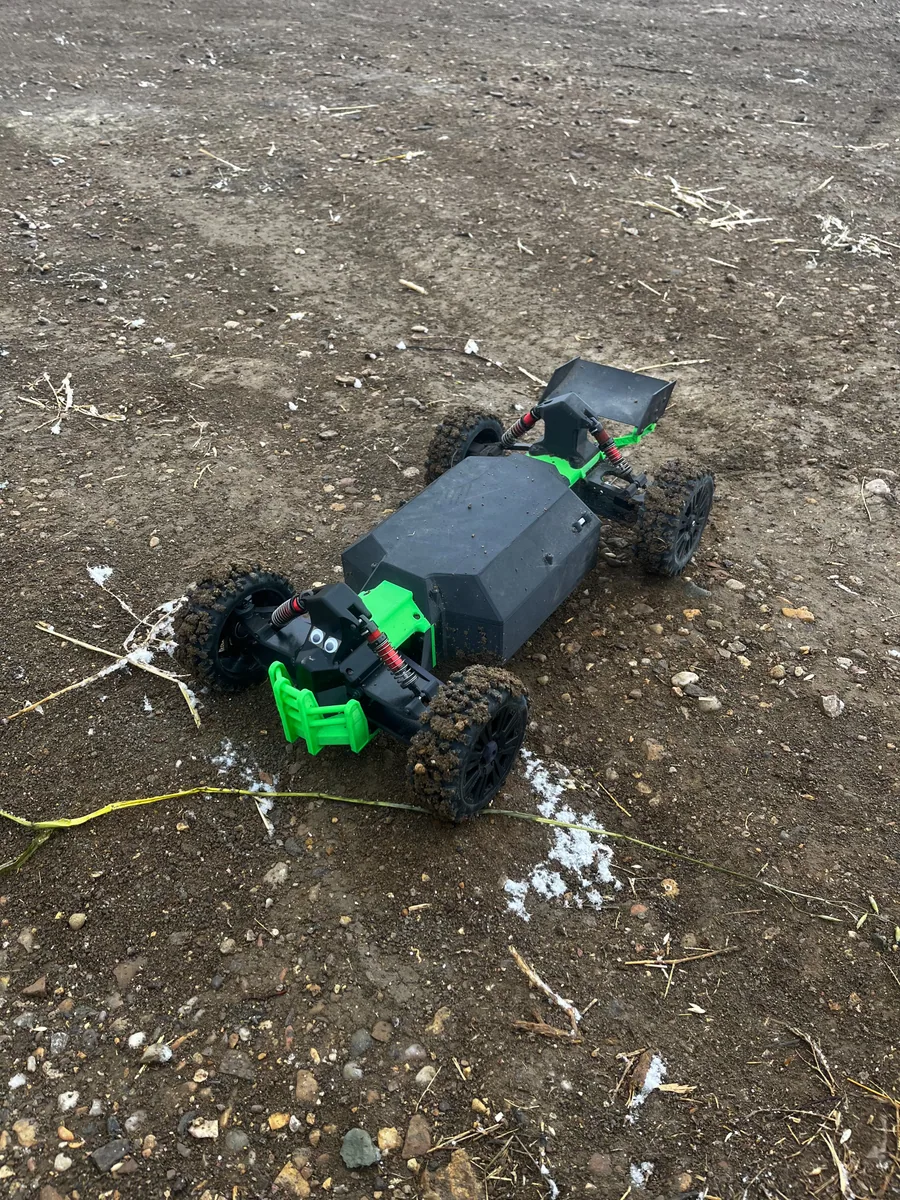
My earlier RC car used a chassis design from online as the platform for learning electronics. For this project, I wanted to design the complete mechanical system myself, including the chassis, suspension, steering system, driveline, and gearbox.
The largely 3D-printed vehicle needed to transmit the output of a 2.8 kW brushless motor, survive outdoor terrain, and remain serviceable as each test exposed a new weak point.
02 / Early components
Prototype the unconventional ideas, then reject the ones that add too much risk.
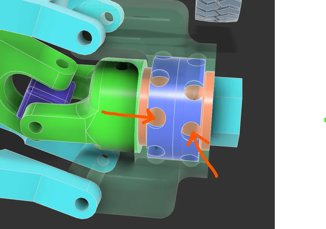
I first designed printed wheel bearings with steel BBs running in precisely printed races. They worked, but the tolerance stack created more play than I was willing to accept, so I replaced them with conventional bearings.
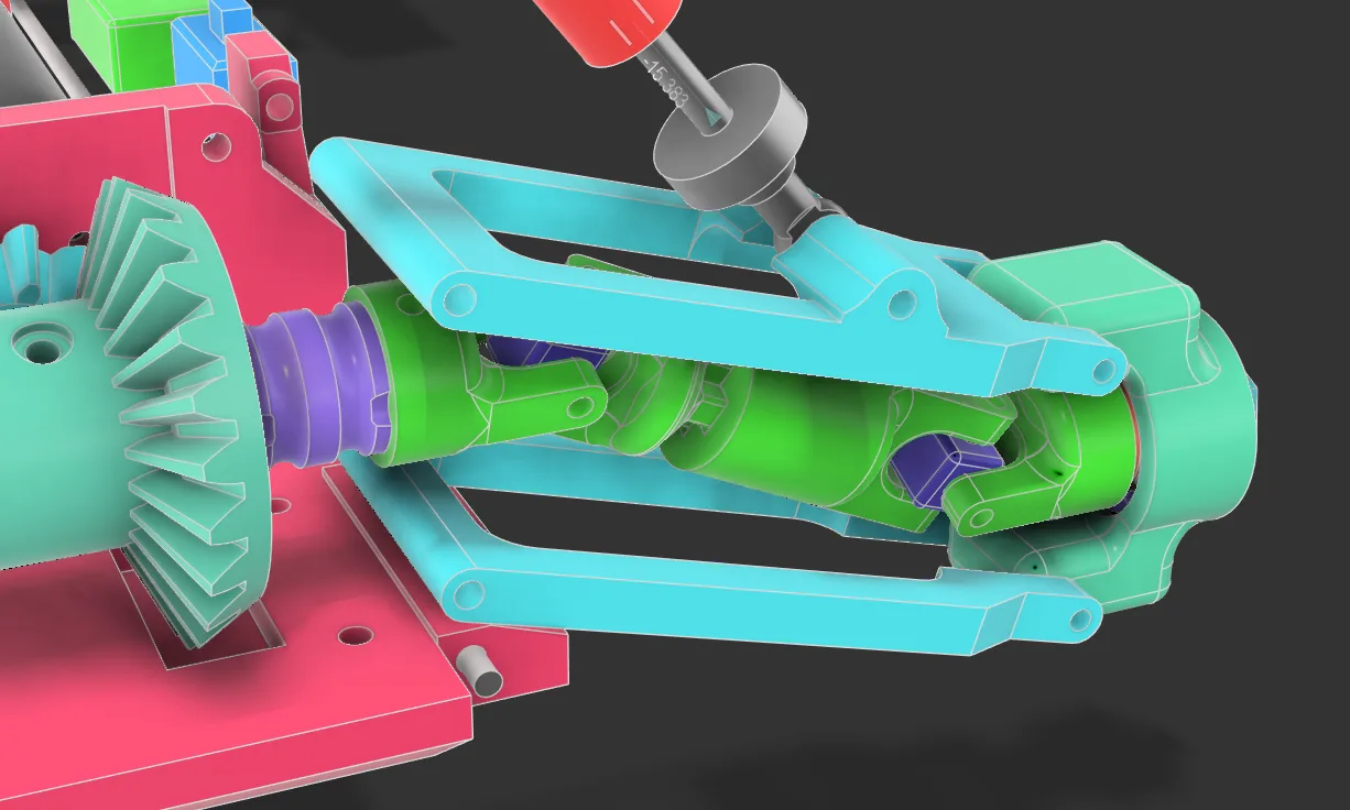
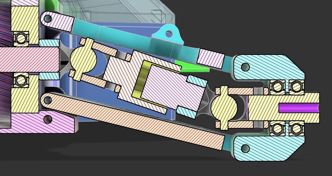
I also modeled and printed universal joints for the rear suspension driveline. The joints broke immediately when power was applied, so they were not a viable option for the roughly four-horsepower drivetrain. I replaced them with inexpensive steel universal joints.
03 / Gearbox development
Turn a stalled first drivetrain into a calculated 14:1 reduction.
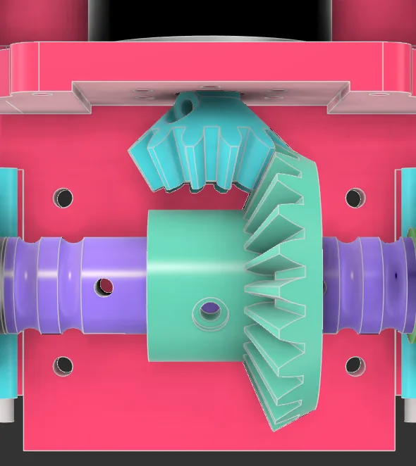
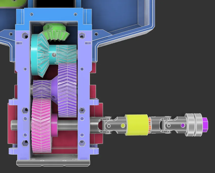
My first gearbox used only a bevel-gear pair and did not produce enough wheel torque to move the heavy vehicle from a standstill. I used the motor specifications and wheel diameter to estimate the reduction required for a target top speed of 20 mph, which led to a 14:1 gearbox with bevel gears, herringbone gears, and steel shafts.
Bench testing revealed another failure mode when the first bevel gear rubbed against the housing. Friction generated enough heat to produce smoke and begin burning the PETG enclosure. I corrected the axial-load problem with needle thrust bearings and did not repeat the failure.
04 / Driveline integration
Package articulation, power transmission, and suspension travel in one assembly.
The final rear driveline combined steel universal joints with an iterated polycarbonate slip-spline shaft. I modeled the full vehicle in Fusion 360 with assembly and motion tools to identify interference through the suspension travel.
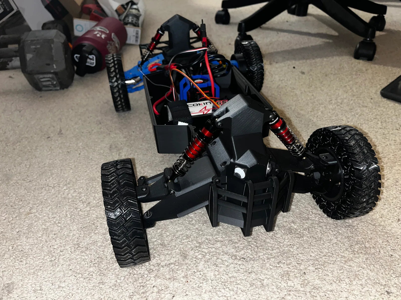
The completed 250-plus-part assembly integrated the drivetrain, steering, suspension, a 3S 5,200 mAh 80C LiPo battery, and a built-in gyro for high-speed stability.
05 / Field testing
Every broken or underperforming part became a concrete design rule.
The finished car was rugged and stable at speed, but outdoor testing exposed limits that CAD could not predict by itself. A printed wishbone failed under impact, TPU tires lacked useful grip, and early driveline parts wore or deformed under load.
The project taught me how tolerances, material behavior, bearing loads, friction, heat, and serviceability interact inside a large printed assembly. It also made physical failure a normal source of design input rather than the end of an iteration.
Tools and methods
- Fusion 360
- Large-assembly CAD
- Drivetrain design
- 3D printing
- Bearing selection
- Steel shafts
- Field testing